How to Read an Address on Digitrax
JMRI® connects to...
- Digitrax LocoNet®
-
- LocoNet Tools
- LocoNet Simulator
- DS54
- LocoIO
- Command Stations
- DCS52
- DCS240
- Other Command Stations
- OpSw Configuration
- Programmers & Adapters
- PR2
- PR3
- PR4
- LocoBuffer
- LocoBuffer-II
- LocoBuffer-USB
- MS100
- Keyspan USB Adapter
- Networking
- LocoNet Client/Server
- LocoNetOverTCP LbServer
- LocoBridge Adapter
- Standalone LocoNet
- Technical
- Addressing
- Implementation
- LocoNet Power Issues
- Enhanced Slots
- Supported Hardware
- Devices, command stations, networks, and protocols:
- Anyma DMX
- Arduinos
- Atlas Commander
- Bachrus
- CAN Bus Networks
- CBUS®
- C/MRI
- CTI Electronics (Acela)
- CVP EasyDCC
- Dcc4Pc
- DCC++
- DCC Specialities
- Digi XBee
- Digikeijs (Digirails)
- Digitrax
- ESU ECoS
- Fleischmann
- Hornby
- Insteon (Powerline)
- Lenz
- Lionel TMCC
- LocoNet
- Maple Systems
- Märklin CS2
- MERG
- Modbus
- MQTT
- MRC
- NAC Services RPS
- NCE
- Oak Tree Systems
- OpenDCC
- OpenLCB
- Pi Technology RailDriver
- Powerline
- Protrak Grapevine
- QSI Quantum Developer
- Raspberry Pi
- RFID Readers
- Roco
- SPROG DCC
- SPROG DCC Generation 5
- SRCP server
- TAMS Main Control
- TracTronics SECSI
- Uhlenbrock Intellibox
- Viessmann Commander
- Wangrow System Ane
- WiFi Throttles
- X10 (Powerline)
- XPressNet
- Zimo MX-1
- ZTC Controls
- Applications
- Past the community of JMRI.org:
- DecoderPro®
- PanelPro™
- DispatcherPro™
- OperationsPro™
- SoundPro™
- Apps with JMRI connections...
- Jython Apps for JMRI...
- FAQ
- Tools
- JMRI tools for working with your layout:
- Common Tools:
- Throttles
- Turnouts
- Lights
- Sensors
- Signaling
- Consisting
- Reporters
- Memory Variables
- Blocks:
- Blocks
- Sections
- Transits
- Routing and Control:
- Routes
- LRoutes
- Entry Get out (NX)
- Logix
- LogixNG
- Other:
- Sound
- CTC Tools
- Fast Clocks
- ID Tags
- Speedometer
- Timetable
- Where Used
- Organization-specific...
- Common Tools:
- Layout Automation
- Use JMRI to automate parts of your layout and operations:
- Signaling
- Warrants
- Dispatcher
- Routes
- LRoutes
- Entry/Exit Routing
- Logix
- LogixNG
- Scripting
- Automate with Coffee
- CTC Tools
![]() Donate to JMRI.org
Donate to JMRI.org
Support: Digitrax LocoNet®
- Supported Hardware
- PR2, PR3, and PR4 acting as Decoder Programmers
- Hardware Interface and Command Station Limitations
- Connecting
- Using JMRI with LocoNet®
- LocoNet Device Addressing
- LocoNet Tools
- Networked Computers and LocoNet®
- Using JMRI with LocoNet®
- Debugging
- Erratic or Non-Performance CV Readback
- Command Station Turnout Command Rejection and JMRI Turnout Command Treatment
- Turnout Control Handling Settings
- Command Station Turnout Command Rejection Avoidance Strategies
- Turnout command rejection when track power is off
- Turnout command rejection and multiple agile LocoNet connections
- JMRI information and tools for LocoNet-specific hardware and features
- JMRI LocoNet-specific Assistance pages
- Configuring some LocoNet devices via "Roster" entries
- Programming Board ID (Lath Address) for some Digitrax devices
- Some JMRI LocoNet-specific device and feature limitations
- Back up
Supported Hardware
JMRI software, including DecoderPro and PanelPro, works with your Digitrax command station to program decoders. To practise this, it communicates with the command station over the LocoNet® using one of several types of adapter.
Command Stations
JMRI software supports the following LocoNet-based command stations:
- Zephyr Starter Set up
- Zephyr Xtra Starter Set
- Super Empire Architect Ready
- Chief Starter Fix
- Super Primary Set
- Super Chief Xtra Fix
- DCS50 Command Station/Booster/Throttle
- DCS51 Command Station/Booster/Throttle
- DCS52 Command Station/Booster/Throttle
- DB150 Command Station/Booster
- DCS100 Command Station/Booster
- DCS200 Command Station/Booster
- DCS240 Advanced Command Station/Booster
- Intellibox: The Uhlenbrock Central Unit
- Intellibox II or IB-Com
- DCC-Mux: DCC data combiner with built-in LocoNet command station
For systems which practise not provide a real LocoNet Command Station, two boosted options are supported. When a layout uses LocoNet peripheral devices just not a LocoNet-based control station, a "Standalone LocoNet" is used.
In addition, JMRI software may exist configured to use a simulated LocoNet connexion instead of a real LocoNet connectedness. This is the "LocoNet® Simulator".
Computer Interfaces
To connect your figurer to the LocoNet, and hence to the command station, you need one of the following adapters:
- LocoBuffer-NG
- LocoBuffer-USB
- PR3, PR3 Xtra
- PR4
- LocoBuffer II
- LocoBuffer
- MS-100
- Bluetooth LocoBridge
(Notation: The Digitrax DSC240 has a congenital-in adapter that'south similar to the Digitrax PR3; if you take a DCS240 and connect the computer via the DCS240's integrated USB interface, see this DCS240 page. Similarly, the Digitrax DSC52 has a built-in adapter that's similar to the Digitrax PR3; if you lot have a DCS52 and connect the computer via the DCS52's integrated USB interface, see this DCS52 page.
More often than not, whatever of these can be used with any type of computer to communicate with whatsoever type of control station. Currently, the LocoBuffer-NG , PR3, and PR4 are the recommended computer interface solutions. The LocoBuffer Two and original LocoBuffer are no longer commercially available; their main advantage at present is that they use a traditional serial port, which may be the just suitable connection blazon available on some older computers.
The MS100 is non recommended; information technology sometimes fails to provide reliable communications, and it cannot be used with JMRI if you are using Mac OS X or on most Windows Vista machines. If you lot take issues with the MS100, you might not be able to prepare them, and nobody may be able to assist y'all.
The Uhlenbrock Intellibox command stations can also exist controlled directly through information technology's serial port or USB connection; in that location'south a separate page on how to do this.
PR2, PR3, and PR4 acting as Decoder Programmers
JMRI can also employ a Digitrax PR2, the Digitrax PR3, or the Digitrax PR4 to program and examination decoders. The PR2 is a stand-alone decoder programming unit of measurement which does not connect to the residual of the layout, the command station, nor to a LocoNet. For more data on using a PR2 with DecoderPro, please see the PR2 setup folio. The PR3 and PR4 devices can be configured in JMRI to operate every bit either a stand- lone developer, or as an interface to to a LocoNet. There is more information on the PR3 setup page and the PR4 setup folio.
Hardware Interface and Command Station Limitations
Uhlenbrock Intellibox - The Intellibox has two LocoNet connections, called LocoNet-T and LocoNet-B. The LocoNet-T connection can drive more devices, only does not provide the Rail-Synch signals that some LocoNet devices (specially boosters and the BDL16, BDL162 and BDL168) require. A LocoBuffer should be continued to the LocoNet-T connexion.
Uhlenbrock Intellibox Two and IB-Com - The Intellibox 2 and IB-Com have two LocoNet connections, chosen LocoNet-T and LocoNet-B. The LocoNet-T connexion can drive more than devices, just does not provide the Rail-Synch signals that some LocoNet devices (particularly boosters and the BDL16, BDL162 and BDL168) crave. A LocoBuffer should be connected to the LocoNet-T connection.
PR-1 not supported - Note that DecoderPro cannot directly program decoders via a PR1 developer. JMRI supports decoder programming either via the PR3 every bit a stand up-lonely programmer or via a command station.
Mac OS 10 and the MS100 - Because Mac OS X can't communicate at the special baud charge per unit used past the MS100, the MS100 won't work with Mac Bone 10. You should go a LocoBuffer-NG or LocoBuffer-USB instead.
Microsoft Vista and the MS100 - Information technology has been reported that Vista does not back up the special baud rate used by the MS100. If you find that your MS100 does not work on your Vista machine y'all should get a LocoBuffer-NG, LocoBuffer-USB, PR3, or PR4 instead.
Connecting
To connect your estimator to a Digitrax DCC organization, you demand either a USB-equipped Command station (DCS240 or DCS52), or a computer-to-LocoNet adapter device such as a LocoBuffer-NG, PR3, PR4, LocoBuffer-II, LocoBuffer or MS100. The LocoBuffer-NG is a highly recommended estimator-to-LocoNet adapter. See below for more than on adapters.
Note that except for the PR3 and PR4, these are just LocoNet interfaces, non stand up solitary programmers like the Digitrax PR2. The Digitrax PR3 and PR4 devices may act either as a standalone programmer or equally a LocoNet interface. Readback of decoder CVs is possible when using a programming track controlled past a PR3 or PR4 (in stand up-alone programming mode) or when using a programming track controlled by a Primary, Zephyr, Advanced (DCS210) or Evolution (DCS240) command station. The Empire Architect (DB150) control station does not allow Readback of decoder CVs; users of the Empire Builder tin can add CV Readback capability past using a programming rail connected to a PR3 or PR4 when operating in stand up-lonely programming manner.
Basic steps to connect to LocoNet
If connecting to a DCS240 control station via its integrated USB port, see these instructions for configuring JMRI for the DCS240.
If connecting to a DCS52 command station via its integrated USB port, see these instructions for configuring JMRI for the DCS52.
The steps below bear witness how to add together a connection to JMRI (DecoderPro, PanelPro, etc.) for a LocoNet-based system.
- If using a LocoNet adapter, connect your adapter to the LocoNet, and connect your calculator to it with the appropriate serial or USB cable.
- If using a command station's USB connection, connect your computer to your control station with the advisable USB cable.
- Mac and Windows users should install the proper USB drivers if they are using USB devices.
- Linux and Mac users should be sure that the correct Java communications packages accept been installed.
- Open up a JMRI program and get to the "Preferences" console. This normally opens automatically the first time each plan is run, or you can select it from the "Edit" card. Alternately, if you already have 2 or more connections established and at outset-upward you become a choice box for the connection profiles, you may choose to establish a new connection contour and the "Connections" window will automatically open up (then you may skip the next footstep).
- Select the "Connections" item in the window at the left.
- Select "Digitrax" in the "System Manufacturer" box.
- Select the appropriate adapter type (or command station blazon, if using a computer-to-command station USB port connexion) in the "Organization Connection" box.
- Y'all tin can so configure the proper settings in the "Settings" box. The "Serial Port" must be properly selected and the connection settings properly configured in club for JMRI to talk to the adapter hardware. On some systems with some system connection adapter types, the "Serial Port" setting will be automatically selected. In other cases the kickoff possible "Serial Port" connection will exist selected by default. It may be necessary to utilise tools provided with the reckoner operating organisation to determine which "Serial Port" is appropriate for your item situation.
- Select the advisable "Command Station Type":
When the "Connection Type" is ready for the PR3 or PR4, the "Command Station Type" can be fix to "PRx in stand-alone programming mode" or set to one of the command station types. When gear up for stand-alone programming, the PR3/PR4 will not communicate with LocoNet. When prepare for a specific command station type, the PR3/PR4 programming rail is not used; instead, decoder programming is done through the mechanisms provided by the selected command station, and its programming runway connections.
When "DB150 (Empire Builder)" is selected, JMRI decoder programming is done via the DB150 programming mechanisms. The DB150 is non capable of reading decoder CV values, so JMRI volition not exist able to read decoder CV values via the DB150 programming mechanisms. Empire Builder users tin can use a PR3/PR4 in stand-alone programmer way, instead of the Empire Builder programming track, to allow decoder CV readback. Some users configure DecoderPro for programming decoders using the PR3/PR4 in stand-lonely programming mode, and then configure PanelPro to use the PR3/PR4 in LocoNet interface mode (as well chosen "MS100 mode") to allow PanelPro to communicate with the Empire Architect command station and LocoNet-connected peripherals. More PR3 setup data can be found on the PR3 setup page. More PR4 setup information can be found on the PR4 setup page.
- The "Connection Prefix" is used to aid JMRI communicate separately with multiple "connections" to layout hardware. Each "connexion" must have a unique identifier, which is specified equally the "Connection Prefix". By default, the first LocoNet connectedness is given a prefix of "L", and additional LocoNet are given prefixes like "L1", "L2", ... Most users should exist able to use the default "Connectedness Prefix" value provided by the JMRI tools.
It is recommended that all connections for LocoNet hardware utilise a prefix that begins with "Fifty", as other characters are normally associated with other hardware connexion types. - When a JMRI tool is configured for more than than one connection, each connectedness gets a carte du jour detail on the main JMRI tool window. To help users differentiate between their different connections, each connexion has a "Connection Proper name", which is used as the proper noun of the associated bill of fare detail on the primary JMRI tool window. Users may change the "Connexion Name" for any connection to suit their needs.
- Some adapters may have improver configuration options, which appear by checking the "Boosted Connection Settings". This may show boosted settings applicable for some adapter types. These include, only are not limited to, the options listed here.
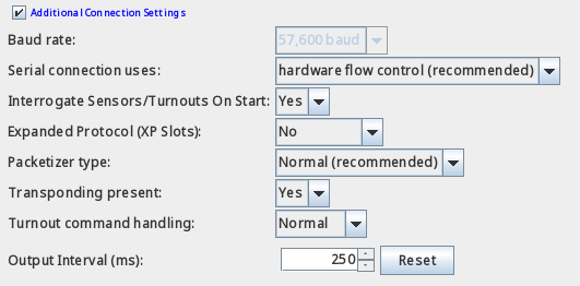
- The "Baud rate" setting. When multiple settings are available, this must be set to match the needs of the detail hardware adapter specified in the "Arrangement Connectedness" setting. This setting will exist pre-set and unchangeable you have selected a LocoBuffer-NG, LocoBuffer-USB, PR3, PR4, or MS100 "Organisation Connection". There are 2 speed choices for the LocoBuffer and LocoBuffer-2; select the one that corresponds to the jumper settings on your LocoBuffer unit of measurement. We recommend that y'all beginning with the 19,200 choice for the LocoBuffer or LocoBuffer-2; run across the LocoBuffer-II and LocoBuffer pages for more information.
- The "(Serial) Connection Uses" selection determines how "flow command" is implemented in software. This selection should exist configured for "hardware menstruum control" unless you lot subsequently consistently get a JMRI panel message about the LocoBuffer control leads being improperly gear up upwards, in which case y'all might desire to endeavor to bypass that by selecting "no flow control".
This box will be blank if y'all've selected LocoBuffer-NG, LocoBuffer-USB, PR3, PR4 or MS100. - Packetizer Type lets you cull Normal (recommended) or Strict.
- "Transponding Present" allows you indicate whether certain special hardware is nowadays and configured. If you accept LocoNet-attached boards that configure in "ops mode", or if you have Digitrax Transponding installed, ready this to "Aye". Otherwise, prepare it to "No".
- The "Command Station Turnout Command Rejection and JMRI Turnout Control Handling" settings are described beneath.
- Output Interval sets a configurable (minimum) interval for all turnout outputs that are office of a Route or Output Matrix Signal Mast on this same connexion.
Use the [Reset] button to restore the default of 250 ms. No restart is required after a alter.
- Click "Save". You'll be asked if information technology'southward OK for the plan to quit, click "Yes".
- Restart JMRI. Y'all should be up and running.
If you lot are going to control Turnouts, Signals or other devices on your layout from JMRI or another program, we recommend that you disable, where available, the control station'due south "Meter route/switch output when not in trinary" feature. When enabled, this choice profoundly reduces the number of commands the LocoNet can handle each second, which can cause meaning delays when you're controlling signals, etc. To disable it, you can use the "Configure Command Station" tool in the LocoNet card, or the Roster-based mechanism, or the throttle-based programming mechanisms every bit described in the manual for your command station. The control station may not immediately take OpSw setting changes, so it may be necessary to "power-wheel" the command station, or to "put the command station to slumber" via the command station front end-console switch.
Annotation that some command stations disable metering (i.e. provide faster turnout command treatment) when OpSw31="t" and others when OpSw31="c". Here's a list of command stations and the OpSw31 setting which volition speed-up command station turnout command handling:
- DCS100/DCS200 - OpSw31="t" for faster turnout command handling (i.e. disables metering)
- DCS240 - OpSw31="c" for faster turnout command handling (i.e. disables metering)
- DCS210 - OpSw31="c" for faster turnout control handling(i.e. disables metering)
- DB150 - does not provide a way to control "metering"
- DCS50 - does not provide a way to control "metering"
- DCS51 - does not provide a way to control "metering"
- DCS52 - OpSw31="c" for faster turnout command treatment (i.e. disables metering)
- DT200 interim as control station with DB100 - does not provide a way to control "metering"
If you will accept multiple connections, the "Defaults" tab in the "Preferences" console may be used to directly certain types of operations to different connections. A good instance of this is a system with two PR3 connections, one in stand-lone programmer manner for programming decoder CVs, and the other for advice with a layout LocoNet and command station. In this case, employ the "Defaults" settings to select one LocoNet connection just for "Programmer" and the other LocoNet connectedness for "Throttles", "Ability Control", and "Command Station".
Using JMRI with LocoNet®
JMRI provides a number of features which let information technology to interact with LocoNet. Some key things to know about are included here.
LocoNet Device Addressing
Many LocoNet devices can be directly addressed by JMRI, such as the private turnout outputs on a DS54, or the individual block detection inputs on a BDL16x. For more information on how to notice those addresses, encounter this page.
LocoNet Tools
JMRI provides a variety of LocoNet-related tools. These primarily allow configuration of LocoNet device functionality, but likewise include some tools for condition monitoring. Information on these tools tin can exist constitute at the LocoNet® tools page.
Networked Computers and LocoNet®
There are several mechanisms available to permit multiple computers to communicate with LocoNet. These communicate via standard TCP/IP protocols, and can even piece of work remotely. At least one of the networked computers must have a functioning LocoNet interface. See this page for more than information.
Debugging
- When using the LocoBuffer or LocoBuffer-II, exist sure that the JMRI preferences for the connexion are gear up to use the aforementioned Baud rate as the LocoBuffer or LocoBuffer-2.
- On Windows O/S machines, be sure that the JMRI connection is set to utilize the correct COM port. Utilize Windows "Device Manager" to help determine which COM port your interface hardware is using, and then verify that JMRI is configured to use that COM port.
- On Windows platforms, the COM port assignment can change if the interface hardware is moved from i USB port on the computer to another USB port. Avoid changing how your LocoNet-to-computer interface is connected to the computer.
- On Windows platforms, the COM port consignment tin change if the interface hardware is connected via a USB hub. At Windows commencement-upward, the computer tin can assign unlike COM port numbers to devices downstream of USB hubs, even if all of the USB hardware connected in the system has not been changed. Avoid connecting your LocoNet-to-computer hardware downstream of a hub. Annotation that a figurer monitor which has USB connectors, and which is connected to a PC using a USB cablevision is considered to have a congenital-in USB hub.
- Some PR3 devices were shipped with poor quality USB cables. These cables have been known to cause a reckoner to fail to communicate with the PR3 or to have intermittent communication. Users should consider replacing the original USB cablevision from the PR3 with a known-proficient USB cable.
Erratic or Non-Functioning CV Readback
- Some mobile decoders will merely let proper Readback of CV values when there is a sufficient electrical load connected to the F0F (front headlamp) output connections or the motor connections. This means that an incandescent lamp or LED is properly connected to the front headlamp connectedness and functional. Other mobile decoders will simply provide proper CV Readback when a motor is connected to the mobile decoder motor connections. Consult the documentation for your mobile decoder to determine what connections are required to let proper CV readback.
- Some Digitrax hardware is capable of successful CV read and write operations on some mobile decoders but is unable to reliably read and/or write CVs for other mobile decoders. This problem is most obvious with sound decoders from some manufacturers. Some suggestions are listed here.
- When using a Zephyr (DCS50) or Zephyr Xtra (DCS51), enable its "Nail Way" programming feature. This will often permit correct writing of mobile decoder CV values.
- "Programming on the master" can allow a Chief (DCS100 or DCS200) to properly write to difficult mobile decoder'due south CV values.
- A programming booster, such as the SoundTraxx PTB-100 or the DCC Specialties Power Pax can often be used between the command station programming runway connections and the programming rail to allow successful read and write admission of CVs on mobile decoders which do not permit Readback on a programming track connected directly to the programming hardware.
- Some PR3 users report that the PR3 programming track can successfully read and program sound decoders when the PR3 is powered using an 18 Volts DC power supply instead of a lower-voltage ability supply such as the PS12 or PS14. Do this at your own risk! Current Digitrax documentation for the PR3 defines a maximum input voltage of xv Volts DC, where previously the maximum voltage was listed equally 20 Volts DC. Use of input voltages higher than 15 Volts DC could damage the PR3 hardware.
Command Station Turnout Command Rejection and JMRI Turnout Command Treatment
Digitrax control stations pass LocoNet switch command messages to the DCC track indicate then that track-continued accessory decoders tin receive the switch commands. Digitrax command stations seem to buffer the switch requests and forwards them to the DCC track signal in a way that does not have a noticeable impact on mobile decoder response to throttle control operations. This buffer is limited, and under conditions of heavy LocoNet switch command traffic, tin overflow. When this happens, the command station will respond with a bulletin (a \<LONG_ACK\> opcode) saying that it rejected (did not accept) the switch command. When the command station gives this response, the switch command is not placed into the buffer and is forgotten.
This tin can be problematic, depending on how the device which sent the switch command responds to the rejection bulletin on LocoNet. Many LocoNet devices do not find the rejection bulletin, so exercise not attempt to re-send the switch command. Other LocoNet devices can pay attention to the rejection message and tin expect a while earlier re-sending the bulletin. Some LocoNet devices tin can be programmed either to resend the switch command if the rejection message is seen, or to non resend if the rejection message is seen.
This wide diverseness of behaviors can cause inconsistent or unreliable beliefs of any device which relies on stationary decoder messages on the DCC track signal. Note that this can include devices which connect to LocoNet and which monitor the DCC track signal which is available on the LocoNet cable "RailSync" wires.
- Turnout Command Treatment Settings
JMRI has diverse mechanisms to help handle these temporary LocoNet switch command buffer overloads. These mechanisms are controlled past the "Turnout Command Handling" choice for each LocoNet-based connection. The four JMRI Turnout Command Treatment options are described beneath.
- Normal - the default setting, is recommended for the vast majority of layouts. In this mode of operation, JMRI will rapidly retry the last LocoNet switch control seen earlier the command station's switch command rejection message, and will continue to repeat the switch command until a switch command is accustomed by the control station. This quick retry tin crusade extremely high levels of activity on LocoNet.
- Spread - This mode is the aforementioned as "Normal", described to a higher place, except that JMRI implements boosted delay between any switch commands which it sends to LocoNet. This should reduce the likelihood that JMRI commands would cause an overflow of the Digitrax command station switch control buffer, but does not have whatever effect on other LocoNet devices which generate LocoNet switch commands. The retry machinery described above for the "Normal" mode is enabled.
- One Only - This disables the JMRI retry mechanism for rejected switch commands. JMRI volition not retry whatever LocoNet switch control messages. The amount of delay between whatever two JMRI-generated switch commands sent to LocoNet is the same as "Normal" fashion.
- Both - This option both disables the JMRI rejected switch command retry mechanism and increases the delay between any two switch commands sent by JMRI to LocoNet.
These options do non take effect until the preferences are saved and JMRI is restarted.
None of these options can guarantee that all LocoNet switch messages volition be passed to the DCC rails bespeak. - Command Station Turnout Command Rejection Avoidance Strategies
There are a number of strategies which tin be used to avoid the "turnout control retry storms" which tin can occur with JMRI.
- Practise not use "flashing" bespeak aspects when signal hardware does non provide the flashing mechanism. When the hardware does non provide an appropriate flashing mechanism, JMRI must manually change the point head aspect from "a lit colour" to "dark" and repeat for the elapsing that the signal head displays a flashing aspect. This is a trouble that occurs with JMRI when using SE8C betoken heads, and can occur with other signal head types.
Alternatively, in some cases it may be possible to configure the signaling hardware so that JMRI need not send frequent individual turnout commands to implement flashing aspects. While this selection may exist useful with some signaling hardware, this pick does not apply to JMRI when using SE8C betoken heads.
- Some users observe it possible to take reward of the JMRI "automation" feature which uses a unlike machinery to control switches. With a LocoNet connectedness, this mechanism uses LocoNet messages which are specifically sent to the DCC track signal. These messages are neither the "normal" LocoNet turnout command messages nor the "alternate" LocoNet turnout control messages used with the control station "Bushby" feature, described below.
See Turnout Tabular array "automation"help for more than data on this mechanism.
When using this machinery with LocoNet connections, the turnout must not exist configured for "MONITORING" feedback mode, as the messaging used with this mechanism does not utilize the messages required by "MONITORING" feedback mode. This may be done in the JMRI "Turnout Table" past setting a turnout'due south "Feedback" mode to i of "Direct", "OneSensor", "TwoSensor", "Indirect" or "Verbal" (choose one depending on the usable fashion), and then configure the "Turnout Automation" mode to "RAW".
The image beneath shows one possible configuration which takes advantage of this JMRI characteristic for a LocoNet turnout.
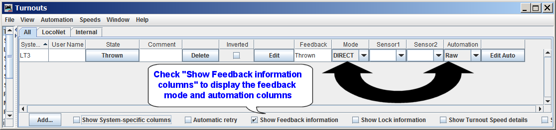
(Click the epitome for a larger version of the paradigm.)
The effect of this setting is to (potentially) reduce the maximum rate at which the command station must forward LocoNet turnout control messages to the DCC track signal. This (potentially) reduces the demands on the command station's buffering, thus potentially reducing the likelihood of the command station's buffer filling.
When this manner is used for a given turnout, JMRI does not make any employ of the "Bypass Bushby Bit" or the "Transport ON and OFF" configuration information.
This blazon of JMRI configuration does not impact those LocoNet turnout control letters generated by other LocoNet devices.
In that location is some question about how Digitrax command stations handle the messages associated with this mechanism, which must exist buffered by the command station, and whether that control station buffering is whatever unlike than the buffering used with "normal" and "alternating" LocoNet turnout messages.
- JMRI commonly sends an "ON" LocoNet bulletin followed by an "OFF" LocoNet message when controlling switches, just like Digitrax throttles do. Since JMRI 4.15.7, it is possible to configure JMRI to transport but "ON" messages to turnouts, without sending "OFF" letters. Many accessory decoders work well when simply receiving "ON" messages.
Using this JMRI feature reduces the number of LocoNet switch control letters which demand to be forwarded to the DCC track signal, which reduces the probability that whatever given LocoNet switch command volition make it at the command station when its buffer is already total.
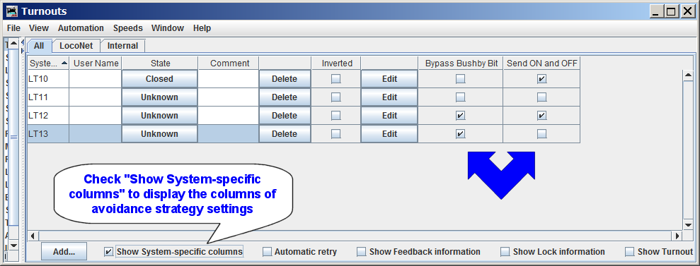
To configure this JMRI operating mode, information technology is necessary to configure each individual JMRI turnout, via the JMRI "Turnout Table". The image below shows that turnouts LT10 and LT12 are configured to send both "ON" and "OFF" messages - each of these turnouts have the "Send ON and OFF" checkbox checked. In the image, turnouts LT11 and LT13 accept the checkbox unchecked, then JMRI will just send "ON" messages when JMRI controls these turnouts.
 .
.(Click the image for a larger version of the prototype.)
If the "Send ON and OFF" column is not visible, y'all may bank check the "Prove System-specific columns" checkbox at the bottom of the window, or you may "right-click" while pointing to whatever visible header and and so check the "Transport ON and OFF" checkbox.
When a new JMRI turnout is created, the "Ship ON and OFF" checkbox is checked by default.
Notation that the "Transport ON and OFF" checkbox settings have no effect LocoNet switch control messages sent by other LocoNet agents.
- It is possible to configure Digitrax command stations so that they practice non forward "regular" LocoNet turnout command messages to the DCC runway betoken (and RailSync wires on the LocoNet cable). This may be done by enabling the command station'southward "Bushby" characteristic, typically done by configuring the control station'due south OpSw27 to "c"losed. JMRI provides two methods for modifying Digitrax control station OpSw settings. Both are described in this Control Station Configuration aid page.
When the command station "Bushby" feature is enabled, only turnout commands using a special LocoNet bulletin type volition be forwarded to the DCC track signal. This tin be used in a few dissimilar ways.
- Some users simply enable the command station "Bushby" feature, without re-configuring any LocoNet device or JMRI features. In this case, no turnout control messages are forwarded to the DCC rails point past the command station, and those devices which go their command data from turnout commands on the DCC runway signal (or the depression-power version on the RailSync wires on the LocoNet cable) will not be controllable.
This option is simply suitable for layouts where there are no devices which are controlled solely past the DCC runway signal (or its depression-ability equivalent on the LocoNet cable.
Note that some devices get their command letters from the low-power DCC track signal on the LocoNet RailSync wires or from the LocoNet Data wires. If this type of device must be controllable when the control station'due south Bushby characteristic is enabled, the device must be configured to get control letters from the LocoNet Data wires. An instance is the SE8C, which defaults to receive control messages from the low-power DCC runway indicate on the LocoNet cablevision. To configure the SE8C to be controlled by LocoNet messages, set up the SE8C OpSw14 to "C"losed. Other device types may require similar re-configuration to be controllable.
- Since JMRI 4.15.7, JMRI provides a feature which "bypasses" the command station'due south "Bushby" feature and therefore allows JMRI to control those devices which are controlled by turnout control information on the DCC rail signal. This requires configuration of private JMRI Turnouts (via the "Turnout Table") to have their "Bypass Bushby Chip" checkbox checked. This enables JMRI to ship "alternate" LocoNet Turnout control messages to the command station, and these "alternating" messages will be buffered so that they may be passed to the DCC track signal, regardless of the country of the command station'due south "Bushby" feature.
To configure this JMRI characteristic for a turnout, ascertain the turnout (if necessary) in the JMRI "Turnout Table", and place a cheque in the turnout'south "Bypass Bushby Chip" checkbox. If the "Bypass Bushby Scrap" column is not visible in the table, yous may correct-click on the table column header row and bank check "Featherbed Bushby Bit", or check the "Prove system-specific settings" checkbox at the bottom of the window.
In the image above, turnouts LT12 and LT13 testify the "Featherbed Bushby Bit" checked. When JMRI attempts to control either of these ii turnouts, JMRI will send an alternate LocoNet turnout control bulletin ("OPC_SW_ACK"), which will bypass the command station's "Bushby" blocking of "regular" LocoNet turnout command messages ("OPC_SW_REQ").
Annotation that the command station still buffers the "alternating" LocoNet turnout control letters, and turnout message rejection can occur. Every bit such, it is important to configure the "Bypass Bushby Bit" option only on those turnouts which require conrol via the DCC track point or the low-power version that is available on the LocoNet cablevision's RailSync wires.
As well note that setting the JMRI "Bushby Chip Bypass" feature a given turnout does not affect how turnout control messages from other LocoNet are encoded. Unless another LocoNet device uses the "alternate" LocoNet turnout command message, that LocoNet device will non be able to pass turnout control messages to the DCC track signal when the control station "Bushby" feature is enabled.
- Since JMRI 4.25.2, JMRI includes a simple script to provide forwarding of "normal" LocoNet turnout control messages, for sure user-defined addresses, as equivalent "special" LocoNet turnout control messages. This can be useful when the command station'south Bushby feature is enabled, and certain devices get their control messages from the DCC rail point or from the "RailSync" signals. See the LnBushbyForwarder.py script aid page for details and information on how to configure it for your layout.
- Some users simply enable the command station "Bushby" feature, without re-configuring any LocoNet device or JMRI features. In this case, no turnout control messages are forwarded to the DCC rails point past the command station, and those devices which go their command data from turnout commands on the DCC runway signal (or the depression-power version on the RailSync wires on the LocoNet cable) will not be controllable.
- The best turnout command rejection avoidance strategy is one in which the control station never even sees the LocoNet turnout control messages. This can be done by using only devices which send and/or receive switch control messages via the LocoNet data bus, and placing all of those devices on a "Standalone" LocoNet for employ by those devices. This standalone LocoNet tin be separately connected to JMRI (on a 2nd connection) so that JMRI can admission the command station, throttles, fast clock, and other resource via one LocoNet connection, and access signals and turnouts via another LocoNet connexion. This requires a separate LocoNet interface device for each connection.
See the JMRI Standalone LocoNet® page for background, ideas, and suggestions for implementing a Standalone LocoNet.
- Practise not use "flashing" bespeak aspects when signal hardware does non provide the flashing mechanism. When the hardware does non provide an appropriate flashing mechanism, JMRI must manually change the point head aspect from "a lit colour" to "dark" and repeat for the elapsing that the signal head displays a flashing aspect. This is a trouble that occurs with JMRI when using SE8C betoken heads, and can occur with other signal head types.
- Turnout command rejection when runway ability is off
Some more recent Digitrax command stations will pass up to have switch commands when track power is turned off. This can result in a "storm" of repeated switch messages on LocoNet if track ability is off when switch letters are sent. This problem tin be avoided by ensuring that track ability is on when switch letters are to be sent.
- Turnout command rejection and multiple active LocoNet connections
When JMRI has multiple active connections to a unmarried LocoNet, it may be necessary to configure all merely one of the active LocoNet connections for "Turnout Control Handling" type of "Only One", with ane active LocoNet connection configured for 1 of the other "Turnout Control Handling" types. Failure to do this could cause the various JMRI LocoNet connection instances to independently try to resolve any turnout messages which have been rejected past the command station. This could event in a storm of turnout command retries on LocoNet.
Similarly, when multiple JMRI instances are working with the same LocoNet, only one JMRI connection to the LocoNet should be configured for a "Turnout Control Handling" type other than "Just One". Failure to do this could cause the various JMRI LocoNet connectedness instances to independently endeavor to resolve any turnout messages which have been rejected by the command station. This could result in a storm of turnout control retries on LocoNet.
JMRI data and tools for LocoNet-specific hardware and features
JMRI supports a wide diversity of LocoNet hardware and features. JMRI provides a broad variety of hardware-specific tools to assist in configuring the devices. And JMRI provides a number of tools to monitor the operation of LocoNet. Virtually of these features are described in the JMRI "Assistance" pages linked below (also refer to the sidebar).
JMRI LocoNet-specific Help pages
- Calculator-to-LocoNet® Interface Hardware
- RR-CirKits LocoBuffer-NG
- RR-CirKits LocoBuffer-USB
- RR-CirKits LocoBuffer-2
- LocoBuffer
- Digitrax PR4
- Digitrax PR3
- Digitrax PR2
- Bluetooth LocoBridge
- Digitrax MS100 (Strongly not recommended)
- Digitrax DCS52 via its integrated USB port
- Digitrax DCS240 via its integrated USB port
- LocoNet-related Tools
- Monitor LocoNet
- Monitor Slots
- Monitor Clock
- Monitor LocoNet Stats
- Configure BDL16x
- Configure DS64
- Configure PM4x
- Configure SE8C
- Configure LocoIO (No longer supported, preferred method is via DecoderPro3)
- Roster-based Command Station Configuration (recommended), or the Configure Command Station Tool
- Configure LocoNet ID
- Configure Duplex Group. (Note that this tool can have an consequence on LNWI devices.)
- Send Throttle Message
- Ship LocoNet Packet
- Select PR3 Mode
- Download Firmware
- Download Sounds
- Voltage and Electric current Meters
- 3rd-political party Command Stations
- Fleischmann Twin Centre
- Uhlenbrock Control Station
- Other LocoNet-related information and features
- JMRI addressing of LocoNet® Turnouts, Sensors and Transponding zones
- LocoNet® Simulator
- Connecting multiple computers to a LocoNet® layout
- Connecting Multiple Computers to LocoNet® via LBServer
- Connecting Multiple Computers to LocoNet via LocoNet® Server
- Standalone LocoNet
- JMRI Loftier-level Structures for LocoNet® Interfacing
- A technically-oriented study of Power Supply bug in some Digitrax products
Configuring some LocoNet devices via "Roster" entries
Some LocoNet devices tin be configured via JMRI a "roster" entry. Simply select the appropriate "decoder" name when creating a new roster entry. These include:
- DCS100/DCS200/DCS50/DCS51/DCS52/DB150/DCS210/DCS240 (only when acting every bit a command station)
- BDL16/BDL162/BDL168
- DS64
- PM4/PM42
- SE8C
Often, these "decoder" definitions take some limitations on which features tin be configured, and, where appropriate, limitations on the supported range of "board id" values. These limitations are documented on a "Notes" tab inside the "comprehensive" programmer window.
Note that JMRI generally provides other (historical) tools which are able to configure the same set of features via tools in the "LocoNet" menu. Whatever changes made to device configuration using the historical tools will not exist reflected in a roster entry for the device. If you wish to keep the roster updated with any changes made via historical tools or using other tools or processes, information technology will be necessary to manually update the roster entry.
Programming Board ID (Board Address) for some Digitrax devices
Some Digitrax devices can be configured for "Board ID" number (sometimes called Board Address). This value is typically used to influence which Turnout, Sensor, Reporter, and/or Power Manager section numbers are used by the device.
Digitrax devices which make utilise of "Board ID" numbers, only which cannot exist programatically configured, include:
- Digitrax DS64
- Digitrax BDL16, BDL162, and BDL168
- Digitrax PM4, PM42
- Digitrax SE8C
- Digitrax BXPA1
- Digitrax BXP88
For these devices, JMRI cannot configure the Board ID number under JMRI's control without user intervention. It is, nonetheless, possible to configure the Board ID number using JMRI and transmission intervention. The process is to follow the directions found in the device transmission for changing Board Accost (Board ID), only employ JMRI'southward "Turnout Control" tool instead of a LocoNet throttle.
Beneath is a table showing, on the left, the Digitrax instructions copied from the BDL168 manual, and, on the right, the instructions when using JMRI. Similar instructions may exist used to configure other the Lath Accost (Board ID) on other Digitrax devices.
| Step/th> | Digitrax Instructions for changing BDL168 Board Address | Instructions for changing Lath Address (Board ID) when using JMRI |
|---|---|---|
| 0 | (A stride not included in Digitrax documentation, but one that is necessary regardless of what method you use!) 0. Ensure that NO OTHER Activity is occurring on LocoNet! If anything causes generation of a LocoNet Turnout Command message after the device button has been pressed, but before you outcome the turnout control bulletin to the specific number you desire, then the board volition be configured to use that unexpected turnout number, leaving the board unmanageable at the Lath ID number you are expecting! Be aware that movement of trains on layouts where signaling is implemented tin can cause generation of LocoNet Turnout control messages! | |
| 0.25 | Configure JMRI to communicate with with your LocoNet hardware. | |
| 0.5 | Run into Annotation 1 below earlier proceeding. This step applies both for the Digitrax procedure and the JMRI-based procedure. | |
| 1 | Notation: Steps 1 thru 4 of the Digitrax instructions are from Department "8.1 To gear up the BDL168 lath address" of the Digitrax BDL168 manual, with some comments added past JMRI developers.) | Power upward your layout, BDL168, and start JMRI. |
| Power up your BDL168. | ||
| 2 | Press the switch backside the green ID LED for about 1 second, and so release information technology. The greenish ID LED will blink. The red pick LED volition not calorie-free. This allow's you know that you lot are in board address fix up mode. (Note: These instructions apply to BDL16, BDL162, and BDL168 devices. Other instructions, buttons, and LED color/flashing conditions may apply for other device types. See the appropriate manual for device-specific instructions!) | Same as per Digitrax instructions. |
| iii | Connect a DT or UT serial Digitrax throttle to the BDL168's LocoNet connector. (This tin just be washed with a Digitrax LocoNet throttle or equivalent software). | Open JMRI'due south "Turnout Control" tool, via "Tools->Turnout Control" |
| 4 | Go into SWITCH mode on the throttle. Select the switch number that corresponds to the lath accost you want to prepare and issue a closed "c" command to gear up the board address. The board address is changed as soon as you issue the SWITCH command. See following instructions for using specific Digitrax throttles for setting the address. (Those instructions omitted here.) | Enter the switch number which corresponds to the board address yous want to ready in the number entry box below "Turnout" at the height of the JMRI "Turnout Control" tool. As an example, to set Board Address (Lath ID) to 4, enter "4" (without quotes". And then activate the window's "Closed" push button. |
| 5 | (A JMRI-specific step, non included in Digitrax documentation, which applies regardless of which method yous use.) See Note 2 below for important data on JMRI behaviors which may influence how JMRI sees the device and which may crave changes to any pre-existing JMRI uses of affected Turnout, Sensor, and/or Reporter configurations, and/or customized scripts monitoring for LocoNet Power Management messages. | |
| vi | Quit and Restart JMRI. See Annotation 3 below, for more information on why this tin be of import. | |
| Note 1 | Some devices, past default, become their turnout control messages from the DCC track signal, and rely upon the control station to forward the LocoNet turnout control letters as DCC track signal stationary decoder packets.
| |
| Note 2 | The Board ID number typically implies the Turnout, Sensor, Reporter, and/or ability management "addresses" used by the device. Changing the Board ID number typically forces the device to use different addresses. This can mean a disruption to the JMRI functionality which worked earlier the Board ID number was changed. If you lot take used "User Names" to reference those items, it is usually sufficient to requite a similar User Name to each "relocated" Turnout, Sensor, or Reporter object, and and so change each reference to the erstwhile object User Name to reflect the new User Proper noun. | |
| Annotation 3 | If JMRI has "pre-populated" the Turnouts or Sensors tabular array with information nigh the device, information technology will exist necessary to quit and restart JMRI so that whatsoever information that was "pre-populated" from the device based on its sometime Lath ID value volition _not_ be remembered. Restarting JMRI causes JMRI to asking the "pre-population" information, and if the device responds to the request, the device should respond with its information and the Turnouts and/or Sensors table should be pre-populated. | |
Afterwards completing the instructions as noted above, the device should be configured for the selected Device address.
Some JMRI LocoNet-specific device and characteristic limitations
-
At this time, Digitrax "expanded" slots are non directly supported. This has several implicaitons:
- The Monitor Slots tool is simply able to display information for "standard" slots. Information technology is possible when using a DCS240 that a loco can be shown as occupying a "standard" slot when it actually is beingness controlled past an "extended" slot. When this occurs, the display volition generallly be "corrected" inside a few minutes.
- JMRI tin can take difficulty acquiring and/or dispatching a loco when the loco has been acquired into an "expanded" slot by a throttle with enabled "expanded" slot capability.
As such, many users observe that disabling DCS240 "expanded" slot adequacy can improve some aspects of JMRI "throttle" functionality, including WiThrottle Server funcitonality.
Additional discussion may be found here.
-
At this time, the Digitrax BXP88 and BXPA1 devices exercise not back up a mechanism to allow JMRI to program individual device OpSw settings via LocoNet messaging.
While JMRI cannot provide mechanisms to configure these devices, for their cake detection and transponding features, their beliefs is similar to the BDL16x device. JMRI's existing support for BDL16x block detection and transponding features provides appropriate support for the BXP88/BXPA1 detection and transponding operational features. JMRI's existing support for PM4x power management features provides advisable support for the BXP88/BXPA1 power management operational features.
-
The LNWI similarly does non provide mechanisms to permit JMRI configuration of individual LNWI OpSw settings. Notwithstanding, some LNWI "SSID" information may be influenced by the operations performed past the Configure Duplex Group tool. Annotation that some specific LNWI OpSw settings are able to cake the result of that tool upon the LNWI's SSID configuration.
- LocoNet does not provide whatsoever skillful style to let JMRI to configure the settings of any "booster". Configure boosters using the mechanisms documented by the booster manufacturer.
- The LocoNet "Command Station Configure" tool does not give access to OpSw settings for OpSw 49 and above. This prevents the tool from accessing some OpSw settings on DCS240, DCS210, and DCS52 command stations. JMRI's "Roster"-based command station configuration does not take this limitation. Both mechanisms are described in this folio.
Tertiary Party/Support
- For JMRI-specific questions, including questions almost how JMRI and Digitrax hardware interact, the JMRI users "groups.io" group is very helpful. This is the first identify to get for JMRI-specific help.
- Support for Digitrax hardware products is available through Digitrax, Inc. Digitrax product manuals may be institute here. Note that Digitrax more often than not does non provide support for JMRI software or third-party LocoNet devices.
- Many knowledgeable Digitrax users contribute to the Digitrax users "groups.io" group. If you have a trouble with Digitrax equipment, this is a proficient identify to pose your Digitrax-specific bug. This user's grouping is run by and for Digitrax users. Information technology is non directly supported by Digitrax.
LocoNet® is a registered trademark of Digitrax, Inc.
Source: https://www.jmri.org/help/en/html/hardware/loconet/Digitrax.shtml
0 Response to "How to Read an Address on Digitrax"
Post a Comment